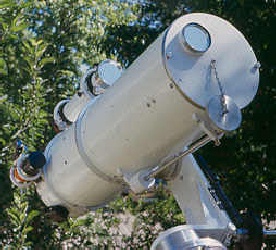
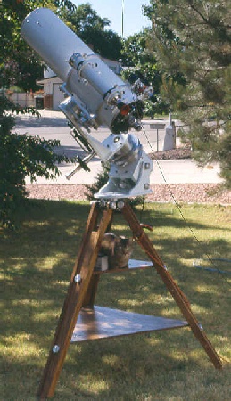
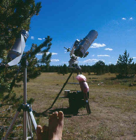
A Rugged Telescope for Rugged Roads
The need to build this 8 inch f/16 Cassegrain telescope resulted from a desire for a portable
replacement
for my old 8 inch f/20, which is sadly the king of non-portable small telescopes.
(See the old heavy-weight HERE)
The required design features of this new telescope were as follows (listed in no particular order):
- No-tool setup and takedown.
- Firm vibration-resistant optical mountings to maintain collimation on rough roads.
- Optical tube that is sealed against dust and moisture during transport.
- Well baffled light path for high contrast even during daytime use.
- Stable mount with siderial drive and slow motion controls on both axes.
- Accurate setting circles to enable daytime planet viewing.
The paragraphs and pictures below show the result. With the exception of the wooden tripod legs, the entire project is made from aluminum plate and sand castings poured in my front yard. Most of the metal came from scrap computer equipment acquired for free.
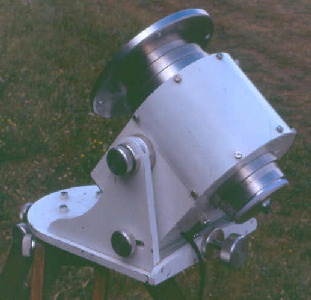
The Optical Tube Assembly
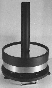
The tube itself is a section of 10 inch diameter aluminum pontoon from a scrap yard. The wall thickness is about 1/10 inch. Each end is fitted with cast aluminum end rings to stiffen the tube as well as provide firm mounting points for the backplate and dust cap. The tube is attached to the mounting of choice by two large aluminum clamp rings fitted with four 3/8-16 studs and matching knurled knobs.
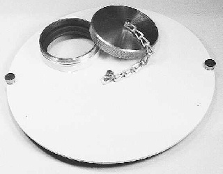
Since the route to the remote observing site I use a lot includes about 15 miles of dusty, rough, washboarded, winding mountain road, a prime concern was that the tube be sealed against dirt and dust. For this reason the backplate was designed as a solid casting. The backplate has an off-center hole bored into it to fit a small electric cooling fan mounted inside. The fan port is provided with a metal cover that rotates out of the way by loosening a captive thumbscrew. The sky end is equipped with a close fitting cap held tight with a pair of captive thumb screws that thread into the tube's end ring. This dust cap is equipped with an off-axis port that is sealed with a screw-on knurled cap that is retained with a length of chain. This port is internally threaded to accept a 2.5 inch solar filter.
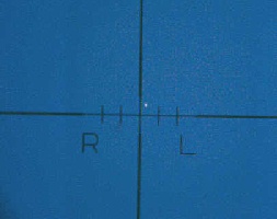
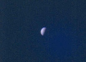
The large 16x66mm finderscope is equipped with a similar filter incorporated into its dust cap. This finder is made from surplus optics, fitted with a crosshair reticle, and is mounted to the main tube with a pair of 3.5 inch ID cast aluminum rings. It can be instantly removed and replaced with any other telescope up to about 3.5" diameter with aligment to the main tube maintained. Below is a view of Venus through this finder under a daytime sky after being located with the setting circles. The view on the right was then shot through the main telescope.
The smaller ~9x45mm finder is also made from surplus optics and is fitted with a graduated reticle illuminated with a red LED. Its eyepiece does double duty as a guiding eyepiece in the main telescope for long exposure photography. A small battery box for the illuminated reticle attaches to the main tube with Velco placed at a couple of convenient spots around the back end of the main tube. The mounting rings of this finder are joined by a short length of dovetail rail which mounts a red dot finder with dimmer.
The sky end of the tube assembly is also provided with a counterweight that slides along a 1/2 inch stainless steel rod to provide balance when a camera or other heavy accessories are mounted at the back end. Several pairs of threaded holes are placed at strategic places along and around the tube for mounting various other finders and accessories that may be needed from time to time, including an independently pointable fluid head on which to mount a camera for piggy-back photography. Unused holes are plugged with cap screws.
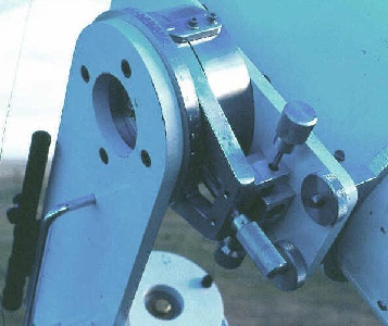
The Backplate, Primary Mirror Cell, and Baffle Tube:
A serious fault found in many Cassegrain telescopes is the practice of mounting the baffle tube directly to the primary mirror. This makes it impossible to align the baffle tube with the mechanical axis of the telescope separately from the optical aligmnent. Ideally, of course, the two should be identical but in reality this is almost never the case, resulting in poor performance due to bad optical collimation (as well as a stressed primary mirror) which in turn is due to poor mechanical alignment.
This practice of mounting the baffle tube directly to the primary mirror can also result in a chipped or broken mirror. I know of three separate occurances of this, one of which was my own. Naturally, for a telescope intended to be thrown in the back of a pickup truck and taken over long rough roads to a remote observing site, this method of baffle mounting would not be acceptable. For a more in-depth discussion and photo's of this issue, click HERE.
In a nut shell, my method of baffle tube mounting goes like this:
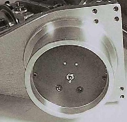
- The baffle tube is mounted directly into a central cylinder extending from the backplate of the tube assembly. This backplate carries the focuser as well.
- The backplate (and hence the baffle tube) can be brought into alignment with the mechanical axis of the tube with three sets of push-pull screws mounted around the edge of the backplate. This points the baffle tube directly at the secondary mirror.
- The primary mirror is held in a cell which is free to slide along the baffle tube and tilt for optical collimation independent of the backplate/baffle tube. This allows optical collimation independent of mechanical collimation - something which the typical mounting scheme fails to provide.
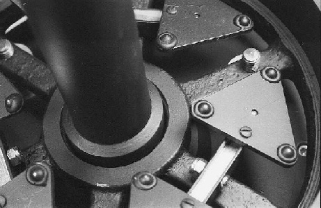
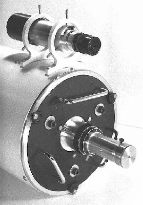
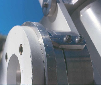
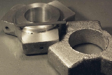
The photo on the right shows the complete backplate/mirror cell/baffle tube assembly ready for installation into the end of the telescope tube. This whole assembly can be removed and reinstalled without the need for recollimation of the telescope.
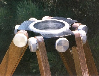
The photo on the left shows how the mirror cell is mounted to the backplate. A 1/4 inch thick rubber O-ring is recessed into the inner diameter of the central part of the cell's spoked casting. This provides a firm but flexible point for the mirror cell to pivot and slide against the central cylinder of the backplate. The baffle tube is inserted into this central cylinder and retained with a single set screw. The three collimation screws extend downward in this view through the backplate. As you can see, I made the cell in the 18-point configuration. The mirror is held in the cell with a large retaining ring that adjusts down with three pairs of push-pull screws to bring its three rubber pads to within a few thousandths of an inch of the mirror's surface.
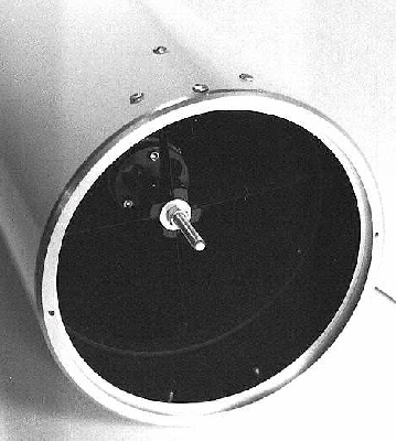
The Secondary Mirror Mount and Spider Assembly:
The secondary mirror is held in an adjustable cell which extends a short distance from the mirror to serve as a secondary baffle. The outer diameter of the cell is threaded to reduce grazing reflections. The tilt adjustment is accomplished by three screws surrounding a single central spring. This cell is mounted to a threaded rod which passes through the aluminum spider hub and provides mirror separation and back-focus adjustment.
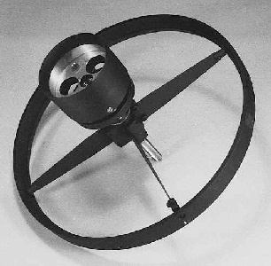
The spider vanes are of 0.015 inch brass, tapered and terminating in pinned threaded couplings. These hold the spider permanently centered in a cast aluminum stiffening ring via four flat head screws. This whole assembly slides into the main tube and is held in place by three screws. This scheme has served well and has held the secondary motionless now for about six years and hundreds of miles of rough roads and has not once required re-collimation since the first time it was installed.
The Mount
The Siderial Drive Base:
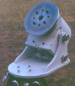
The base of the mount is made mostly from 1/2 and 5/8 inch alumimum plate screwed together. The latitude is adjustable through about 20 degrees centered on 40 north. Adjustment is made by loosening the two knurled knobs on each side of the base and turning a large knurled knob on the south side fixed to a 1/2-20 shaft with a large bearing on the end that presses against a concave portion on the base of the siderial drive box. The baseplate is mounted to a cast aluminum cylinder that fits inside the tripod head. Inside this cylinder are a pair of AA batteries, a bright green and a bright red LED, and a center-off double throw toggle switch to select which of the LED's illuminates the upper tripod shelf beneath it. (I prefer the green but usually use red to keep other nearby astonomers from whining.)
The polar axis of the drive base rides on large wheel bearings from a semi-tractor trailer and is fitted with a 359 tooth worm wheel driven by an AC synchronous motor through a set of step-down spur gears. On the north (top) end of this axis is a 9 inch diameter disk of 1/2 inch aluminum plate that was faced off on the lathe to be flat and perpendicular to the rotational axis. There is no provision for slow motion or slewing on this axis. It is simply a heavy duty siderial clock platform to which other items may be mounted.
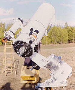
The Fork Mount:
The item most often mounted to the siderial drive base is this single arm fork mount. It is here that the slow and slew motions in R.A. are found. The fork arm is made of two pieces of 5/8 aluminum plate held together by a number of 3/8 inch allen-head screws and a pair of angle braces made from 1/2 inch plate. A small rifle scope is mounted to the fork arm to aid in polar alignment, along with a chrome handle to provide a balanced and convenient point from which to carry the assembly.
The declination axis is identical to the R.A. axis and consists of heavy wheel bearings from a semi tractor trailer mounted in aluminum castings. The tangent arms for the slow motions are castings fitted with 7/16 fine pitch rods that serve to lock the arms to the central castings by putting pressure against nylon inserts set into the arm to serve as "brake shoes", thereby eliminating the possibility of any metal-on metal galling. The threaded rod that provides the slow motion is then mounted in ball bearings fit into an aluminum bracket that is fixed to the saddle plate to which the optical tube is mounted via four knurled knobs (or to the base of the fork arm on the R.A. axis). Both slow motion's tangent arms are fitted with the "cylinder block" type nut assembly. (For more on the cylinder block tangent nut, click HERE).
The numerals stamped into the declination setting circle are upside down for the southern declinations and upside right for the northern. This allows easy determination of whether the telescope is pointed north or south of the equator when viewing objects near it.
A 9 inch disk identical to the one at the top of the drive base's RA shaft forms the base of the fork mount and mates to the disk at the top of the siderial drive base with four large knurled knobs. These knobs engage four studs made from 3/8 inch flathead screws that are threaded through the top disk.
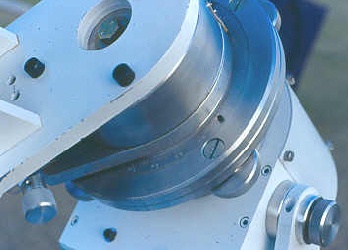
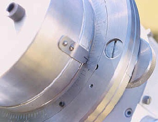
Recessed into the top of this disk is the R.A. setting circle, inscribed with 24 hours in 5 minute divisions, which slips smoothly between teflon and polypropylene rings for the initial setting of the night. As long as the drive remains running, this circle serves as a direct-reading setting circle for the polar axis and the telescope can be slewed from object to object. During the daytime this circle can be initially set by the sun. From there it is simple to slew to Mercury, Venus, Mars, Jupiter, and Saturn (in a clear high altitude sky). This slip ring is fitted with four tiny allenhead screws that serve as handles to push the circle for adjustment. One of these is visible in each of the photos above.
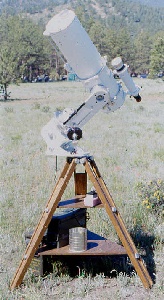
The Tripod:
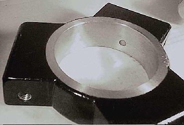
The head of the tripod is a solid aluminum casting bored out to a standard diameter to accept any of several mounts. Once the castings are poured they are cleaned up on the lathe and with a file, then drilled, tapped, and painted. Three 3/8-16 knobs spaced around the head put pressure against round nylon inserts which serve to clamp the cylindrical mount adapter in place. One of these inserts is visible in the photo on the right below.
A set of interchangeable cylindrical inserts was cast to provide a standardized interface for various mounts. Anything I want to mount on one of these tripods can be fitted with one of these inserts which then makes it instantly fit any of the tripods.
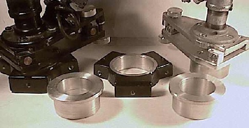
I made seven of these heads so that I could have a variety of tripod heights to use with different mounts as needed without the hassle of changing legs or being limited to using only one telescope at a time. Most of my mounts currently fit these heads and are interchangeable. The cylindrical adapters each contain downward-pointing LED's, one red and one green, with batteries and a center off double throw switch to select which LED illuminates. These are very handy for lighting maps, eyepieces, or other accessories placed on the accesory shelf beneath the mount.
The tripod legs are each attached to the head with two 1/2 inch steel bolts fitted with knurled aluminum knobs. Similar bolts hold the tripod's accessory shelves to the legs. The legs are each made of two lengths of 1-3/4 x 3/4 inch red oak. They are then stiffened by a long triangular center section cut from 3/4 inch oak board. These wood pieces are glued and screwed together, then stained and overcoated with five coats of clear polymer.
The various accessory shelves are made of 1/2 inch plywood. Each shelf has three 1 inch wide x 3/8 inch thick aluminum bars bolted to the underside which fan out to the three legs and are bent to the proper angle to mate up against the inner surface of the center of each tripod leg where the 1/2 bolts with knurled knobs capture them.
These are the firmest wooden tripods I have come across - they are heavy but the stiffness makes them worth their weight.
Performance
The optics for this telescope were acquired in a horse trade and came with badly deteriorated coatings. The original manufacturer is unknown though the back of the primary mirror appears to be machine ground flat. After a fresh clean coat of Beral from Clausing they proved to be scratch free and tack sharp when the telescope is cooled down under a steady sky. They typically perform very well up to around 40 or 50x per inch of aperture and under very steady seeing conditions have been used to advantage above that.
The quality of the baffling is made apparent not only by contrasty views of planets in a daytime sky, but also by the telescope's performance on deep sky objects at night. From a dark site at high elevation with excellent transparency, spiral structure can be seen in M51 and the nightly motion of Pluto is an annual favorite to show to folks at star parties. In side-by-side comparisons with a 7 inch AP Starfire using Jupiter and a bright globular cluster as targets, the Starfire had a definate edge, though the Starfire's $10,000 price tag made me glad to keep this telescope. In numerous side-by-side comparisons with a commercial 14 inch Schmidt-Cassegrain of recent manufacture using many different targets there is no comparison - the 14 has never shown anything to advantage over this 8 inch. (Although I think that says more about the 14 inch than the 8 inch.)
When the mount's axes are left unlocked or only slightly clamped the telescope is slewed around easier than the typical Dobsonian. When locked the slow motions are smooth with no backlash. When correctly polar aligned, objects located via the setting circles typically fall within the inner 1/4 of the larger finder scope. The mount has proven to be a very capable platform for long-exposure photography too.
At some point in the future I intend to replace the wooden tripod with steel. As it is, a tug on a tripod leg feels like the scope is solid as a rock, though a view through the eyepiece was initially seen to take two or three seconds to quiet down. The addition of three home made anti-vibration pads for the tipod cut this easily in half.
When the tripod has these pads under its feet, a tug on a tripod leg makes the whole assembly move slightly side to side, but a sharp rap on the side of the tube or focuser is seen to dampen down in about 1 second through the eyepiece. A slight bump of the focuser dampens down in much less than a second.
These anti-vibration pads were made from the end plugs for the storage tubes of large integrated circuits. These plugs are made of a very squishy (silicone?) rubber and measure about 3/4 inch by 3/4 inch by 2 inches long. Each pad is made by wrapping two of these plugs together with duct tape. Cost = $0.
Many people have commented on the solid stability of this telescope, though there is still room for improvement. No telescope is ever finished, though this one has come close.
- Jim Sapp
CLICK HERE to return to Jim's Home Planet