An Easy-to-Make, Non-Binding, High-strength Tangent Arm Nut for Telescope Slow Motion Controls
by Jim Sapp
The Background:
The typical mechanical solutions to the problem of telescope slow motion fall into two major categories:
- The worm and wheel (or a sector thereof).
- The tangent arm.
The former method can offer a full 360 degrees of travel and is the preferred way to provide siderial tracking, but for fine manual control it requires a large radius worm wheel which can be expensive, heavy, difficult to implement with simple tools due to the required degree of precision, and an inefficient use of material.
When only a small degree of movement is required, the tangent arm is much easier to implement with simple tools and provides fine slow motion at greatly reduced weight and cost. The typical layout consists of an arm temporarily clamped to the axis housing of the mount. The end of the arm farthest from the mount's axis carries a threaded nut through which passes a threaded rod (the lead screw). The lead screw (threaded rod) is captured in a bracket which is attached to the tube of the telescope (or other part to which the slow motion is to be imparted). Turning the lead screw pulls the nut (and hence the arm) toward one end of the screw, providing the desired slow motion.
The Problem:
The primary difficulty encountered in using this method is the tendency of the nut to bind against the lead screw when it approaches either end of the screw, since the movement of the end of the arm naturally describes an arc in relation to the straight line described by the lead screw. This limits the length of travel and results in rapid wear of the nut and/or screw, which eventually leads to backlash and a sloppy fit.
This binding is caused by two main factors: As the arm/nut approaches the end of the lead screw,
- The arm's end (and hence the nut) becomes placed at an increasing distance from the axis of the lead screw.
- The axis of the nut is tilted at an increasing angle in relation to the axis of the lead screw.
This problem is usually overcome by mounting the nut with a pivoting pin (which allows the angle of the nut's axis to remain aligned with the lead screw) to a slug which can travel a short distance in a slot milled into the end of the tangent arm (which in effect allows the arm's length to adjust, maintaining the position of the nut in relation to the lead screw's axis).
However, this presents a number of difficulties to the telescope maker with limited tooling:
- Milling a slot in the end of the arm accurate enough for the slug to travel in without backlash or binding.
- Mounting the nut to a pivoting pin with enough strength and accuracy to minimize backlash and wear.
Two more, but less severe sources of binding and wear that are not addressed by this solution are:
- Inaccurate placement of the bearing mounts of the lead screw which places the axis of the lead screw tilted in relation to the plane of the arm's movment. This too will throw the nut's axis off in relation to the screw's axis.
- Non-perpendicularity of the plane of the arm's movment to the axis ot the telescope mount, which can place the nut's position off center from the lead screw.
These two items are inobvious at first but can be seen to add additional stress to the nut's pivot pin as well as the lead screw and it's bearings.
A Solution:
Described below is a strong but simple solution that provides accurate captured movement for the nut on all axes and can be implemented with only a drill press using metal or even plastic or wood materials. It eliminates the need to mill a slot in the end ot the arm and eliminates the weakness, rapid wear, and subsequent backlash of the typical nut/pin/sliding slug assembly. I have built several of these units using only a drill press, files, and reamers and have enjoyed excellent success each time.
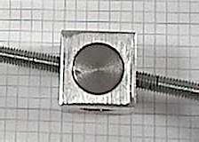
I'll dub this the "Cylinder Block" method. The idea is to provide universal motion for the nut, similar to the way a ball joint works, but limited in travel and well caged for strength. Refer to the photos below.The nut consists of a short length of brass rod that is drilled through the side and tapped to accept the lead screw's thread. This brass cylinder then fits into a hole through the side of a larger steel cylinder, which has a second perpendicular hole drilled through it to clear the lead screw. This steel cylinder then fits into an aluminum block which is drilled and tapped to be fixed to the end of the tangent arm.
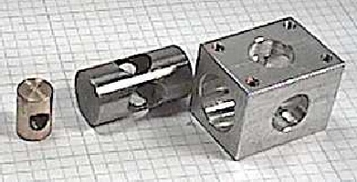
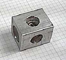
This aluminum cage block is drilled through three axes:
- The long axis is drilled to fit the steel cylinder and allows the cylinder to not only move back and forth like a piston which provides for the "changing arm length" problem, but also to rotate which allows for the "lead screw bearing misaligned with the plane of the arm movement" problem.
- One side is drilled to allow clearance of the lead screw with plenty of room for the lead screw to swing back and forth and up and down.
- The other side is drilled to allow installation of the brass nut cylinder. This also provides clearance for the ends of the nut cylinder to travel a bit on either side of the steel cylinder without running into the wall of the aluminum cage.
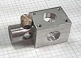
The brass nut cylinder is free to rotate in the steel cylinder which corrects for the angular displacement at the ends of the lead screw's travel, and is also free to slide up and down in the steel cylinder to correct for a bit of displacement of the "tangent arm to saddle plate" dimension. This allows the telescope mount maker a bit of lattitude in the mount's bearing placement without interfering with the function of the tangent arm's mechanicals.
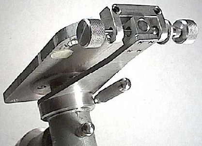
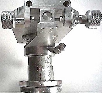
The next set of photos show the wide lattitude of angular misalignment and lead screw displacement that this nut mounting scheme can accomodate. On the left you can see the arc through which the arm can swing without binding the nut, and on the right you can see the amount of lead screw bearing misalignment that can be accomodated. The result is a firmly fixed, solid, and very strong tangent arm nut that is free to float enough to negate a wide variety of improper or missed tolerances in the construction of the mount.
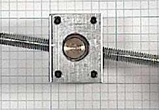
The photos below show a simple implementation of this idea on the declination axis of a German equatorial mount. As you can see, as with most tangent arms, the arm is clamped to the declination axis housing, while the slow motion's lead screw is attached to the mount's saddle plate.
Construction Notes (in no particular order):
- In the assembly photos above, note that the outer edges of the hole in the steel cylinder which provides clearance for the lead screw are countersunk (widened) to allow a greater range of clearance for the lead screw as it swings through its arc.
- Make all parts to a tolerance that allows a tight sliding fit - no slop! This will ensure that there is no backlash in the system.
- Select a tap that matches the lead screw thread well. If the sliding fit of the other parts is well made, this will be the only point at which backlash will show up. A tight fit here will ensure the minimum delay in movement as you turn the slow motion control. Mine have turned out well with negligible delay and no backlash.
- Brass is an excellent choice of materials for the nut cylinder whether the lead screw is steel or brass. It has a "self-lubricating" tendency and gets along well with itself as well as steel. Steel or stainless steel are excellent choices for the larger cylinder, since it gets along well with the brass nut and also with the aluminum cage block. Steel is easier to work with than stainless though.
- Use standard sized materials to make your parts. This will eliminate the need for a lathe and milling machine. I usually use 10-32 rod for the lead screw, 1/4 or 5/16 inch brass round stock for the nut, and 3/4 inch steel round stock for the cylinder.
- For best results, drill the holes a bit undersized then ream them to finished size. If you don't have reamers, perfectly good results can be had by drilling the holes slightly undersized then using the finished size drill bit as a reamer. No problem. There will be some deformation of the surfaces of the cylinders around where the holes were drilled through. File these areas of deformation down slowly to effect the desired sliding fit in their respective holes. Be sure to chamfer the ends of the cylinders a bit with a file to ensure there is no binding at that point too.
- Use a deburring tool or scraper in conjunction with a very fine rat tail file to completely deburr the inside of the aluminum cylinder block to ensure there is no galling or binding of the steel cylinder.
- If you are making this out of wood you will need to use much larger stock to ensure good fit and thread strength. You may wish to use nylon round stock for the nut cylinder, and hardwood dowel for the larger cylinder and cage block. I do not recommend using plastic for the larger cylinder or cage block though, due to the large changes in part size that temperature changes will inflict, causing tightness and binding. (This is a serious drawback that I have seen in certain commercially made focusers - they work fine in moderate temperatures, but in cold weather they constrict to the point that eyepieces wont fit and the focuser won't work.) Also, don't finish the wooden parts with paint, shellac, or other coatings unless you are prepared to spend a lot of time with sand paper getting the fit right. Seal the wooden parts well all over with candle wax (parafin) to keep moisture out which will cause the wood to expand and tighten up. The candle wax serves well not only as a seal against moisture, but as a great lubricant too. Note that I have never made one of these from wood. Those are just my "horse sense" recommendations to those that might give it a try.
I hope this little idea helps to give the reader great success in constructing a fine telescope mount. It has worked very well for me and even after many years of use these tangent nuts remain solid and backlash free.
- Jim Sapp
Summer, 2003
CLICK HERE to return to Jim's Home Planet