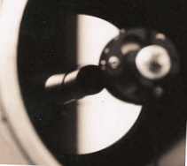

Cassegrain telescopes are noted for their ability to provide high magnification planetary images in a very compact design. Less well known however are the high contrast dark background views of deep sky objects that these f/15 and f/20 systems can provide. But to attain these fine images proper optical collimation is required. Like short-focus Newtonians, Cassegrain telescopes are very sensitive to proper collimation.
I am convinced that the poor opinion of these systems held by some amateurs is unwarranted and due in large part to the common but inadequate method of mounting the primary baffle tube. This not only makes good collimation nearly impossible and tends to stress the primary mirror out of shape (which contributes to poor images), but sometimes even results in the destruction of the mirror.
The final straw was placed on this camel's back one day when my telescope was knocked over (don't ask) and the baffle tube took a large chip out of the front surface of the primary mirror! Mine was not a unique experience as evidenced by the number of photographs of other Cassegrain mirrors with similar chips I have seen on the internet.
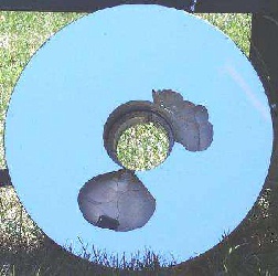
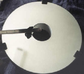
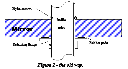
Perhaps you too have been plagued by the shortcomings of this common method which is depicted by the cross-sectional representation in figure 1, and employs a baffle tube whose outer diameter is only slightly smaller than the diameter of the perforation in the primary mirror. This tube is then clamped directly to the primary mirror by means of three nylon screws spaced equally around the circumference of the tube whose heads bear directly against the optical surface of the mirror.
The tube is then retained in the mirror by a flange that slips over the rear of the tube which bears against the back of the mirror and is locked in place with a set screw. There are usually three small foam rubber pads to provide cushioning between the flange and the back of the mirror. This assembly is then placed in a normal mirror cell.
This scheme would probably work fine if the following conditions could be met:
In the case of the off-the-shelf components that I have struggled with on and off for several years, neither condition 1 nor conditions 2 or 3 have been successfully met. This has resulted in poorly shaped star images and difficulty in achieving proper collimation due to the confusion caused by the variable and constantly off-center reflections of the baffle tube when sighting through the system.
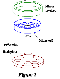
After that disappointing experience I implemented the design described below in the next Cassegrain I built. This design eliminates all of the objectionable features mentioned above and I can see no reason to use the other method ever again! The three major assemblies are pictured together in figure 2. They provide a permanently and accurately aligned primary baffle tube that in no way imparts mechanical stress to the mirror which is safely cradled by an eighteen point support system neatly incorporated into the mirror cell.
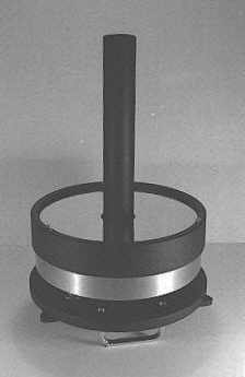
The mirror cell is held centered in the telescope tube by a thick rubber O-ring set into the inner bore of the cell, which allows the cell to slide along the protruding cylindrical portion of the backplate with sufficient travel for back-focus adjustment by the collimating screws. The optical axis of the primary mirror can then be aligned independently of the permanently aligned mechanical axis of the baffle tube, which makes optical collimation much easier. The cross-sectional view in figure 4 illustrates the final assembly.
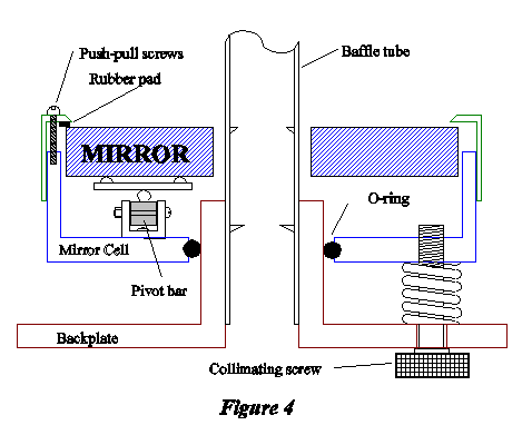
The mirror retainer ring is held to the front of the cell by three sets of push-pull screws, and is fitted with three small rubber pads that are adjusted to within a few thousandths of an inch of the surface of the mirror. When the mirror is assembled into this cell, it makes a convenient package that is ready to be slipped over the baffle tube and joined with the backplate's three collimating screws. The entire assembly can then be installed in the telescope tube as a unit. This has proven to be very convenient.
Since the baffle tube is held securely by the backplate, the only critical conditions that need to be met with this system are:
If the telescope's main tube can not be accurately squared, other provision must be made for squaring on the backplate, such as three sets of push-pull screws placed around the circumference of the backplate that function in the manner of a refractor's lens cell. This squaring on can be checked by sighting through a peep hole in the focuser and adjusting the backplate to bring the skyward end of the baffle tube concentric with the secondary mirror holder (which was previously centered in the tube).
Begin by choosing a baffle tube diameter that is sufficiently smaller than the primary mirror's perforation to allow ample freedom of movement (tilt) of the mirror for collimation and back-focus adjustments without interference from the baffle tube. For instance, if your mirror's perforation is 2 inches in diameter, use no larger than 1-3/4 inch OD tubing. For a 1-3/4 inch perforation, use no larger than 1-1/2 inch diameter tubing, etc.
Next you will need to design the mirror support system so that you can find the working distance from the mirror face to the backplate. This will enable you to determine the remaining dimensions needed for the mirror cell, backplate, and baffle tube.
The old rule of thumb states that standard thickness mirrors of eight or ten inches diameter and larger should have at least a nine point support system (though some would disagree), but for me, an eighteen point system was just about as easy to make and blended well with the casting designs. For thin mirrors eighteen points may be a requirement. Either way you look at it, when mounting optical components overkill is rarely a bad thing.
Using the Hindle method I have computed the dimensions for the support points for a few common mirror sizes and reproduced them in the table below. For those that wish a more modern approach to support point spacing, you may wish to consult the program PLOP which can be found on the internet.
The parenthesized letters can be associated with the labels in figure 3 which shows the layout for the mirror cell.
| (A) Mirror Diameter: | 8 | 10 | 12.5 | 16 |
|---|---|---|---|---|
| (B) Diameter of outer circle of points: | 6.53 | 8.17 | 10.21 | 13.06 |
| (C) Distance apart of outer support points, or length of triangle sides: | 1.69 | 2.11 | 2.64 | 3.38 |
| (D) Radius of circle to envelope triangle: | 0.98 | 1.22 | 1.53 | 1.95 |
| (E) Distance between triangle centers on the pivot bar: | 2.67 | 3.33 | 4.17 | 5.33 |
| (F) Radius of primary 3-point support (where the pivot bars are attached): | 2.31 | 2.89 | 3.61 | 4.62 |
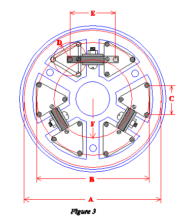
The cell itself is a six-spoked aluminum casting which provides plenty of ventilation to the back of the mirror. The collimating screws thread through three of the spokes and the pivot bar supports are screwed to the alternate spokes.
The center bore of the cell is grooved to retain a thick O-ring of 1/4 inch cross section which fits snugly to the cylindrical center of the backplate, but not so tight as to prohibit the tensioning springs around the collimating screws from effectively doing their job. This O-ring serves not only to center the mirror cell with respect to the backplate and baffle tube while allowing the cell to traverse along the cylinder, but to provide a captive rocking pivot point for collimation.
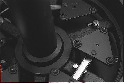
The six triangular plates are made of aluminum. The eighteen support points (three to a triangle) are 1/4 inch steel balls that are held with a dab of epoxy into chamfered holes (made with a center-drill) located at the proper positions on the triangles. The centers of the triangles have similar holes drilled from the back which allow the plates to ride on balls fixed to the pivot bars in a similar manner. The view below shows the triangle details. This picture is of a mirror cell for a different telescope but is of essentially identical construction.
Long small screws (size 4-40) are threaded through the triangular plates near their edges above the pivot bars. These pass very loosely through over-sized holes in the pivot bars to keep the plates from rotating. The screw threads are then smoothed off with a file and the screws are bent slightly to keep them from catching on the edges of their respective holes in the pivot bars.
The pivot bars are made of steel square stock and rock see-saw fashion on screws which pass loosely through them and through the sides of short pieces of similarly sized aluminum channel which serve as supports for the pivots. The pivot screws are held captive by lock nuts with nylon inserts.
As can be inferred from figure 4 above, adjustment of the collimating screws can cause a slight lateral displacement of the primary mirror in relation to the mechanical axis of the telescope just as with any typical mirror cell, but the combination of the O-ring and the over-sized holes in the backplate for the collimating screws holds this to a minimum. Needless to say, the closer the O-ring can be made to the mirror, the smaller this displacement will be. In future castings I plan to make the center part of the mirror cell taller to bring the O-ring a little closer to the mirror, though in practice I have disregarded this lateral displacement as it has proven to be minimal and not really an issue.
The baffle tube is secured in the backplate assembly by a set screw and is internally threaded and provided with a number of internal light baffles just as in a refractor tube.
As with any open-ended reflector telescope, the backplate should be provided with large ventilation holes. This particular telescope was designed to be moisture and dust resistant so I made only one ventilation hole and fitted it with a small electric fan mounted to the inner surface of the backplate with an access door on the rear of the backplate that rotates out of the way to allow air flow. This has worked well.
If you made your parts well, and after your focuser is accurately located on the rear of the backplate, a view through the focuser toward your accurately centered secondary mirror will reveal a wonderfully concentric mechanical system ready for optical collimation - unless you have a little squaring-on of the backplate to do! The difference in performance this simple arrangement can make may very well change your opinion about your old Cassegrain!
Clear skies!
- Jim Sapp
Summer, 1998 (Updated Spring, 2003)