The worm gear itself is simply a screw, captured in place and running in bearings, that accepts the input motion. Its threads engage the teeth of the worm wheel which is basically a disk with partial screw threads running around its circumference. Commercially produced gear sets of this type made on a gear generator and suitable for mounting directly to the polar axle of a moderately sized equatorial telescope mount with the usual number of 300 to 400 teeth typically cost several hundred dollars each.
Very servicable worm wheels can readily be made on the lathe or drill press with a minimum of effort at home. The basic procedure entails constructing a rigid fixture to hold a blank disk that is free to rotate against a standard tap held in the chuck of the drill press or lathe, which serves as the hob for cutting the teeth of the gear. The screw-like action of the tap naturally rotates the disk at the proper rate.
The accuracy of gears made by this method has been called into question from time to time. I suppose this is because of some examples produced by inexperienced craftsmanship; but with care and patience in their production these gears can perform admirably for driving telescope mounts and other apparatus. As with anything, there is a learning curve. I made a few sloppy ones at first and some good ones later. In the paragraphs that follow I will point out some pitfalls to avoid.
The sixty degree thread form of these homespun worm wheels can never have the intrinsic strength of a standard worm wheel which has a squarish tooth form similar to a modified Acme thread, but we're not lifting ore carts up vertical mine shafts with them either. We're simply driving telescopes and other fairly low-horsepower applications. I suppose one could use Acme thread taps as gear hobs if that thread form were really desired, and many people have even threaded, ground, and heat treated their own hobs, or even made hobs from Acme threaded rod, but I haven't seen the necessity as of yet. My gears have been very satisfactory for all the applications I have used them in (though I wouldn't trust one to hold me suspended over that mine shaft!).
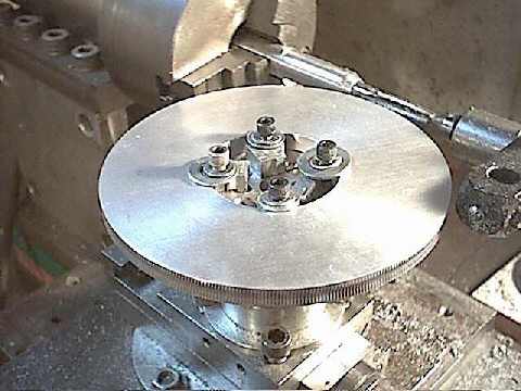
I have successfully made gears of many sizes with the setup pictured here. The compound slide of my homemade lathe was specifically designed with this in mind and was provided with threaded holes on the top for attaching this disk-holding rotating fixture. A fixture could also be designed around an existing tool post. I usually try to support the end of the tap in a small live center mounted in the tailstock for the purpose. When using a small tap against a large wheel blank it is necessary to make an extender to hold the tap far enough away from the chuck to eliminate the problem of the wheel blank running into the chuck.
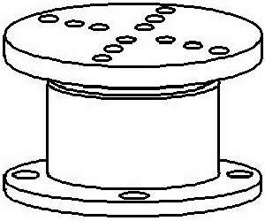
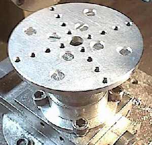
The fixture itself consists of a short pipe nipple which is turned down to match a pair of double-race ball bearings (scavenged from an old vacuum pump) which are set in a larger pipe coupling that is bored to match. The coupling is pressed into an aluminum flange which is provided with four holes in it's base to match the 3/8 inch screws which fasten it to the lathe compound. The upper end of the nipple is fitted with a floor flange which has been faced off to run square and true to the axis of the nipple. This assembly is retained in the bearings by a thin slice of pipe coupling which serves as a nut installed from beneath. Attached to the top of the floor flange is a disk of aluminum plate that is provided with a pattern of tapped holes by which various hold-downs and clamps can be mounted for holding gear blanks of various sizes. A set of disks of various thicknesses drilled with the matching bolt hole pattern are provided to serve as spacers for varying thicknesses in gear blanks. These serve to align the center of the thickness of the gear blank with the rotational axis of the tap or headstock of the lathe. Total cost: maybe ten bucks if you have the bearings on hand. Maybe twenty if you don't.
However you make your fixture, ensure that it is firmly made with no wobble to the axis to minimize chatter and rough or poor cutting action. For very large disks I have mounted an 'out rigger', or additional roller under the gear blank adjacent to where the cutting action is taking place to give additional support to the blank. For best results chose a spiral-fluted tap. These are more expensive but result in a smoother process by reducing or eliminating the interruptions in the cutting action caused by typical straight flutes, though us poor folks do well enough with regular straight flutes.
For a smooth-running gear set the importance of good concentricity of the threads to the shaft can not be over-emphasized! This, and the lack of concentricity in the teeth and inner bore of the worm wheel, are most likely the reasons why some of these home made gear sets have received the bad press that they have. Pay attention to what you are doing here, keep the word concentric in your mind, and you will produce a gear set worth many times over the work that you put into it. Do a sloppy job of it and your gear set will be fodder for the melting pot (or the swap meet!).
Even though I have a lathe that will thread I usually use a piece of threaded rod for my worms anyway, simply because most of the thread is already formed and there is less material to remove when turning down the ends to their finished diameters. I then chase a light cut along the threads to clean them up and bring them concentric with the shaft ends. This reduces the diameter of the threaded rod a bit, but with my method of tap size and rod selection, reducing the diameter of the rod slightly can be beneficial as you will see in the paragraphs that follow. By no means do I claim that these methods are the best, but with limited equipment and some trials and errors it has worked out very well for me.
First of all, face off and center-drill the ends of the rod, then mount it between centers. (Or extend it from the chuck (or collet) only far enough to give you room to turn down the diameters of the worm's two ends, but not so much as to allow the rod to flex excessively from tool pressure which will cause chatter and runout. Then support the end with a live center in the tailstock.) Turn the end's diameters then set up your threading tool and set your change gears to the pitch of the threaded rod. Pick up the thread and make a light cut to bring the threads concentric with the ends. The finished worm is then simply sawn off of the threaded rod with a hacksaw and the ends cleaned up.
Here is how you pick up the thread: While keeping the threading tool away from the work, turn on the lathe and engage the split nut (the lever that engages the carriage to the lead screw of the lathe) as if you were cutting the thread. Allow the carriage to carry the tool to a position anywhere along the length of the threaded portion of your part then turn off the lathe without disengaging the split nut.
Now, using an eight or ten power magnifier (and with the lathe OFF, of course) manipulate your cross-slide and compound to bring the tip of your threading tool into alignment with the threads of the part. By viewing the part and the tool in silhouette against a brightly lit background (a piece of white paper or shiny metal laid under the part), it is easy to get the tip aligned and placed precisely in the thread within one or two thousandths of an inch. Note the reading on your cross-slide dial so that you will know where to set it when making the cut.
Back the tool away from the part, turn on the lathe, and disengage the split nut. You can now move the carriage to the beginning of the thread, set your depth, engage the split nut, and take the cut with confidence that the tool will follow the original thread. It is better to make two or three light passes than one heavy one. Take off only enough material to bring the threads concentric with the ends. If there is any chatter or roughness to your threads, a careful application of a triangular Swiss pattern file and the folded edge of some fine emory cloth at high rpm will shine them up nicely. Later, after the gear set is installed, you should lap the worm against its mating wheel using a very fine lapping compound.
(A cheap and easy lapping compound can be made from abrasive powder (no larger than 400 grit - smaller is better) mixed with axle grease or petroleum jelly. It doesn't take much. A little goes a long way.)
Prolonged lapping will eventually wear a radius into the profile (along the length) of the worm, reducing its center diameter and increasing the number of threads that fully engage the wheel. These work very nicely! But remember to thoroughly clean out the teeth of both parts before the final assembly to remove as much of the abrasive as possible. I use an old tooth brush and a pan of kerosene. Upon final assembly remember to lubricate them.
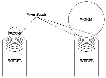
If the wear point is at the bottom of the hollow, the worm will tend to wear further into the wheel which, according to my half-baked reasoning, could eventually cause the reduction of wheel radius and eventually perhaps a reduction in tooth count, just as is observed when making the first and second pass of the tap around the wheel when hobbing.
| Rod Size | Tap Size |
| 3/4-16 | 11/16-16 |
| 5/8-18 | 9/16-18 |
| 1/2-20 | 7/16-20 |
| 3/8-24 | 5/16-24 |
Choices for very small work could be:
| Rod Size | Tap Size |
| 1/4-28 | 12-28 |
| 10-32 | 8-32 |
| 8-32 | 6-32 |
There are even smaller sets that could be tried though I have never had occasion to. Study a tap drill selection table if you are interested. For those that have the watch-maker's bent, it could be fun!
Personally, I have found that using a disk with a diameter computed (with the above formula) for one tooth less than the actual number desired will produce the desired number of teeth - for some combinations of tap pitch and tooth count that is. Other combinations require a disk with a diameter for one tooth more than desired and there are still other combinations that work out just right!
I don't have the mathematical wizardry necessary to pin down an exact formula and I believe that variations in personal technique in the real world have an effect much larger in magnitude than the math would predict. But by trial and error and by recording results I have come to the point where I know my personal style well enough to hit the desired tooth count pretty consistently on some common sizes that I use a lot. I was surprised to find that it is much easier to reliably produce a gear in the 300 to 400 tooth range than one in the 100 tooth range. I can nail a 359 tooth gear (for sidereal drives), or a 360 tooth gear (for solar-rate drives or declination slow-motions) right on the money almost every time, but still fumble around trying to hit 96 or 120. Curious. I suppose there is a math whiz out there that immediately recognizes the reason for this, but it eludes me!
The disk is then held on a ½ inch mandrel in the lathe chuck and the outer diameter brought to size with a 1/16 or 1/8 inch chamfer on each of the disk's outer edges. A facing skim is usually taken to true the accessible face of the disk, then the disk is removed from the mandrel and held in the outer jaws of the chuck, whereupon the central hole of the disk is bored to its desired finished size. The other face is then skimmed true to the bore.
For gear blanks that are larger than the lathe chuck's capacity it is my habit to lay out a smaller three or four-hole bolt circle on the blank that is concentric with the center hole, to which a metal ring of a size within the chuck's capacity is screwed. This ring is then brought accurately concentric with the center hole while the blank is still on the mandrel or in the lathe chuck. Upon removal the assembly is then held by the lathe chuck and the outer diameter and inner bore of the disk are brought to size.
This ring can either be removed and used again, or retained to provide a handy support for a right ascension setting circle - if you are making a clock drive, that is.
Mounting the disk on the lathe's tool-post fixture is the next step, and also the step where the most critical error in making these gears is commonly made.
Place the disk on the fixture with the appropriate spacers to bring the centerline of the disk's thickness level with the centerline of the tap's rotational axis and loosely clamp the disk to the rotating table of the fixture. At this point you will find the utility in the advice to put holes in the disk for this purpose. Tighten your clamping screws only slightly. Using a fixed reference like the tap itself or the edge of the chuck, rotate the fixture while observing the runout of the blank disk about the fixture's axis. Adjust the position of the disk on the table until there is no perceptible movement of the edge in relation to the fixed point as the table rotates. At this point, get out your dial indicator and attach it to a firm area of the lathe (this is where a magnetic base comes in handy) such that it is accessible to the blank disk so that you can 'indicate it in' to precise rotational concentricity with the axis of the table (within 1/1000th inch or better). To do this, exercise patience and the judicious application of a small rubber mallet. Tighten the clamping screws and re-check with the indicator.
It will be your natural inclination to set your indicator against the outer edge of the blank disk.
This could be a FATAL ERROR and one which is commonly made. Here's why:
There are very few lathe chucks that will repeat to better than five or six thousandths of an inch, which is typical. In other words, if one of the diameters was machined, then the part was removed from the chuck, reinstalled, and the other diameter machined, you can rest assured that there is most likely at least five thousandths of an inch runout between the two diameters of your blank. Possibly less, but probably more. This is a lesson to keep in mind when making any part that will require precise concentricity.
If you machined both surfaces (inner and outer diameters) in the same setup without removal, as in the example using the ring, then you have nothing to worry about for they will be very concentric. This would be the preferred method of course, and would allow you to place your hold-down screws within the inner bore of the blank, eliminating the necessity of drilling the extra holes.
But if there is runout in your disk, then it will be important to 'indicate in' the inner bore of the disk. This is the reference point the gear's shaft will see, and the point to which the worm will reference. Rest assured that the tap will take care of the outer edge of the disk, one chip at a time! The illustration below is exaggerated for clarity:
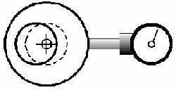
The crossed circle at the center represents the table's rotational axis. The heavy lines represent the outer and inner diameters of the blank, and the dashed circle represents the position that we would like the center bore to be moved to. In this example, we have a two inch diameter blank with a one inch bore, and a nasty lack of concentricity.
As the illustration shows, with the blank in its current position the indicator will tell us that the outer diameter of the disk is running true with the fixture's axis, but look at the center bore. How well is this gear going to perform when mounted on its shaft? Yuk! As you can see, a 1/4 inch error in concentricity means ½ inch variability in tooth engagement! One or two thousandths of an inch variability in tooth engagement can mean the difference between a nice fit (no backlash), and no fit at all.
If this were an actual gear blank, and we were using say, a 3/8 inch tap to cut the teeth, on the high side the tap would break itself trying to worm its way into 1/4 inch of metal, and on the low side the teeth would never even engage the blank. In actual situations there are only a few thousandths of an inch difference between the high and low sides, and by the time the teeth are cut there is nothing left of the original circumference anyway. We are left with a nicely concentric gear, assuming we have accurately centered the center bore with the rotational axis of the fixture's table.
You may have occasion to make a gear where there simply isn't enough room for either your clamp screws or your indicator to fit in the inner bore, yet you know there is runout. Or perhaps your application requires that there be no extra holes in the disk. In these situations I have used my calipers to measure the actual distance between the inner and outer diameters at several points around the circumference, marking them with a permanent marker or scriber. The indicator is then used against the outer diameter and the disk placed at the proper offset to bring the center concentric with the table's axis.
Here's how we work the example from the illustration above: Measuring the 'wall thickness' at a few (6 or 8) points around the circumference, we find that the distance from the outer edge to the inner edge varies from 1/4 inch on the low side, to 3/4 inch on the high side. We mark the high side. By subtracting the inner diameter (1 inch) from the outer diameter (2 inches), and then dividing this figure in half, we find the actual desired 'wall thickness' of our blank:
By subtracting this figure from our high side measurement we find the distance that we must move the center bore toward the high side to bring it concentric with the table's axis:
In other words, we must add 1/4 inch to the high side as read on our indicator, and the points 90 degrees each way around the circumference should agree with each other. Disregard the low side.
Immediately upon tool entry into the metal on the first pass and through the initial portion of the second, I grasp the edge of the disk between my left thumb and forefinger and maintain a slight but steady rotational pressure in the direction that the tap is turning it, with just enough pressure - but no more - to assist the tap in rotating the disk. Only a slight amount of force is needed or even warranted. A small acid brush is used to keep plenty of lubricant on the tap and disk throughout the duration of the cutting process. The brush also serves to remove chips that build up in the flutes of the tap.
On the first time around you will notice that as the cutting action returns to the starting point on the disk, the tap's teeth will rarely (if ever) come perfectly into the first grooves cut by the tap on its first pass, but will find their home in the next few grooves, leaving what looks like double teeth at that point. Don't worry about that. It is the inevitable result of the tap finding its track and will completely disappear by the third or fourth pass with any residual error gradually dispersing and dissipating itself around the disk with subsequent passes.
As the teeth sink deeper into the edge of the disk the pitch diameter of the disk at the tap's cutting depth will shrink and initial tooth count will decrease. It is this possibility for slight variations in tooth thickness that calls for a few extra trips around the disk with only slight tool pressure at the end of the cutting process. Many trips are probably not needed, but perhaps I am superstitious and let it go around several times. According to my reasoning, the more opportunities for high places to be made low and low places to be made high the better the chances for uniformity to be achieved - just as in mirror grinding. Subsequent high-speed lapping of the worm and wheel together in their final mountings will further reduce any residual errors. (Do this by attaching your hand-held drill motor to the worm shaft through a flexible shaft or universal joint.)
I have never had the opportunity to actually measure the uniformity of these gears, but I have made some very nice telescope drives with very smooth tracking rates. The drives with noticeable periodic error have always been the result of runout in the worm or hastily mounted or constructed reduction gears at the motor. Long term (two to four hours, or so) tracking errors have typically been no more than what would be expected by atmospheric refraction. I am very satisfied with my results.
At some point you may need to make a gear and only have one chance to get the tooth count right. There is a technique called gashing that may help you achieve the proper tooth count on the first try. The idea is to make points of least resistance for the hob (tap) to follow that are positioned accurately for the finished tooth. That way the tap's teeth will more easily follow your pre-determined path and wind up back at your expected starting point on the first pass. The tap is then needed primarily to perfect the wheel's tooth form. It usually works, but not always. You can't be chinsy with the gashes or timid with the depth of cut on the first pass.
In a pinch, or for large diameter stuff, you can attach a large protractor to the blank and mount the assembly to the workbench on a center pivot with a good index for the protractor such that the edge of the blank just protrudes from the edge of the workbench. Then use a small saw held against a straight edge clamped to the edge of the bench. It's a lot of extra work and only worth while if you really need a particular tooth count and only have one chance to get it right.
The best way to do this though, is to mount the blank to a dividing head or rotary table on a milling machine or drill press and use a slitting saw to pre-gash your teeth. I use a Dremel tool with a small slitting saw to do the gashing. Of course, to do it this way you need a dividing head, which is another story altogether.
- Jim Sapp