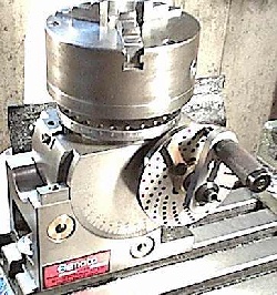
A dividing head is a tool that is used to divide a circle into equal divisions. I am not refering to degrees or radians, so don't think in those units. Think divisions. Have you ever tried to lay out a circle divided into say, 37 equal parts? It's a snap with a dividing head. Pictured below is an example of a typical unit.

In a nut shell, a dividing head is simply a spindle mounted with a precision worm wheel and provided with a crank attached to the worm shaft. The crank's handle is equipped with a spring loaded plunger that will drop an indexing pin into equally spaced holes in a disk mounted behind the crank. The spindle is provided with the means to mount a chuck or collet attachment for holding a workpiece. It is also provided with a lock for clamping the spindle in position for increased rigidity. These units are usually mounted such that the spindle's axis can be tilted through 90 degrees, to provide an additional axis of adjustment.
Most units are made with a 40:1 reduction in the worm, such that 40 turns of the crank will rotate the spindle through one full turn. The indexing plate (the disk with concentric circles of equally spaced holes behind the crank) provides a handy positive index for positioning the crank at 1/n turns of the crank, where n equals the number of holes in the disk. The plunger can be positioned along the arm of the crank to select which circle of holes you wish the indexing pin to engage. These indexing plates are usually interchangeable to provide a wide variety of choices for n, so that one turn of the spindle can be divided into a great variety of equal parts.
The crank is outfitted with a pair of sector arms which can be adjusted to indicate the correct number of holes for any partial turn of the crank you must make. This eliminates the need to count holes on every subsequent advance of the spindle.
Dividing a circle into 40 equal parts is pretty straight forward since the worm wheel has 40 teeth - one full turn of the crank equals one fortieth of a circle at the spindle. To divide a circle into 20 parts: two turns of the crank would equal two 40ths, or one 20th of a circle. One fourth of a crank turn (or 6 holes in a 24 hole index circle) would equal one 160th of a circle at the spindle. Here is the formula:
Reduce this fraction to its simplest form. Use any whole number to represent complete turns, and use the denominator to determine the index plate to use. The last time I checked (just now) index plates with these hole circles were commonly supplied: 24, 25, 28, 30, 34, 37, 38, 39, 41, 42, 43, 46, 47, 49, 51, 53, 54, 57, 58, 59, 62, and 66. These hole circles usually come on a set of two or three plates. Of course, with a dividing head you can make your own index plates. If you make a homegrown dividing head with a worm wheel tooth count differing from 40 you will need to determine your own hole circle requirements. But for the following examples let's assume we have adopted the defacto standard of 40:1.
First a very simple example: we want to mill four flats on the side of a shaft to make a square end to match the square hole in a garden hose fawcett handle we found which we would like to use as a declination clamp on an equatorial mount. So we must divide the circle of the shaft into 4 parts:
It doesn't matter which hole circle we use on the index plate since we have only complete revolutions of the crank to make for each advance of the spindle.
Too easy? Okay, say we want to divide a circle into 360 equal parts for a setting circle:
Take the denominator 9 and determine which of your hole circles it will evenly divide. A quick glance at our list shows we have a 54 hole circle, which 9 goes into 6 times (9x6 = 54). Therefore, 6 holes in our 54 hole circle equals one ninth of a crank turn, which equals one 360th of a circle at the spindle (9x40 = 360).
How about another one? We need to make a bolt hole pattern in an adapter that we want to fit to a surplus space shuttle fuel line flange we scrounged from a high-tech scrap metal yard, which we intend to use as the base of an alt-azimuth refractor mount. Unfortunely this flange has a 13 hole bolt pattern; but fortunately we have a dividing head mounted on our drill press or milling machine table:
Or in other words, 3 turns of the crank plus 1/13th of a turn per division. So to proceed, we set the plunger over our 39 hole circle (3x13 = 39), advance the crank a turn or so to take up any play in the divider, clamp the spindle, drill the first hole, unclamp the spindle, turn the crank 3 full turns plus 3 holes in our 39 hole circle, clamp the spindle, drill the second hole, unclamp, crank 3 turns plus 3 holes, clamp, drill, unclamp, 3 turns plus 3 holes, clamp, drill, unclamp, crank, clamp, drill, unclamp, crank, drill, unclamp, crank...
Easy. Here's a tougher one: divide that circle into 67 equal parts.
Give up? As handy as a dividing head is, there are a few times that you just can't get there from here without a detour or two along the way. For toughies like this there are additional techniques, like compound and differential indexing, involving moving the crank a number of holes in one direction using one hole circle, then turning the crank a number of holes in the other direction using another hole circle, or even rotating the index plate a certain amount. But that is beyond the scope of this discussion. There are also wide range dividing heads that incorporate an additional 100 tooth worm wheel between the crank and spindle. With one of these, divisions between 2 and about 400,000 are possible.
When it comes down to it, either device will do most of what the other will do.
Making Your Own
If (or when) you decide to make your own dividing apparatus, a setup similar to the wormgear-making fixture described in my article on cutting wormgears will be a good starting point. Make a nice worm gear set and mount it to the fixture. You can then use a little ingenuity to mount the worm with a crank and hole circle plate, a clamp for rigidity, and a means to mount a workpiece on top. This will provide the basic functionality for use with a drill press.
The setup I currently use for making setting circles, gashing gear blanks, and other jobs of that nature is similar to the setup described by Allan Mackintosh in Advanced Telescope Making Techniques, Vol. 2.
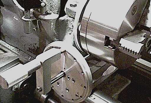
First of all, I made a 360 tooth worm gear set using the technique described in my wormgear making article with the blank bored to match the back of one of my lathe chucks and holes drilled to match the handy bolt pattern already present on the back of the chuck.
Instead of only 40 turns of the crank per revolution of the spindle as with a standard dividing head, this setup requires 360 turns, providing 9 times the resolution (crank turns = 360/N) and also allows quick mental changes between the two concepts of divisions and degrees.
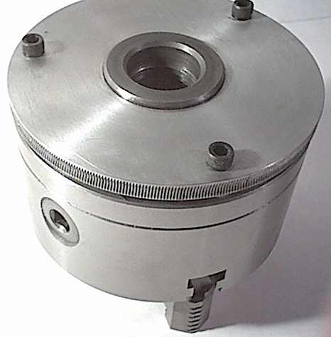
The worm is mounted in bearings contained in a wide U-shaped assembly of aluminum which was made to slide along the lathe ways under the chuck and rotate into position, meshing the worm to the wheel where it is retained in place by a thumbscrew against the back of the far lathe way. The front of the gadget is held firmly against the front of the ways by the back of an index plate which provides the hole circle for a crank's spring-loaded index pin to engage. A small block of aluminum is then fixed to the back of the index plate (with a thumbscrew) which keeps the worm assembly from rotating away and disengaging from the worm. Quick installation, no tools required.
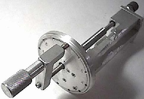
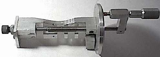
As of yet, I have needed only one 12-hole circle which provides a resolution of 4320 divisions (or 1/12 degree, or five minutes of arc). Half of that, or a resolution of 2.5 minutes of arc, is easily guesstimated by positioning the index pin midway between the index holes. Any item held in the lathe's chuck can now be scribed or gashed simply by mounting the tool on the lathe's toolpost.
For gashing I use a Dremel tool with a small slitting saw. The Dremel is held vertical by an L-shaped bracket held in the lathe's tool post.
This was quick, easy, accurate, and versatile. Worth it's weight in gold. (Well, silver anyway!)
- Jim Sapp