
When it came time to build a binocular mount for leisure scanning of the night sky (or landscape), I decided to build in some features that would provide comfort and convenience. My list of requirements went like this:
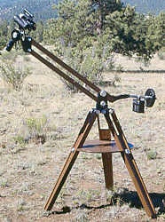
With the advent of the parallelogram mounts, I could see that that design, with some modifications and enhancements, could easily be made to fulfill my requirements and more, so I set about to build one. The photographs and text below show the result of my efforts.
I began by making a short sturdy oak tripod with an integral removable accessory shelf to provide leg bracing as well as a convenient resting place for maps and coffee cups. The tripod head is a solid aluminum casting. The legs are attached with 1/2 inch steel screws fitted with knurled aluminum knobs so no tools are required to tighten it up in the field. The inside bore of the tripod head is fitted with two polypropylene rings that are inlaid into internal circumferential channels bored into the inside wall. These, with a tiny dab of silicone grease serve as bearings for the main azimuth movement to ensure that there is no aluminum-on-aluminum friction to prevent galling. There are also three knurled screws threaded into the head that bear against nylon inserts which apply pressure to the rotating cylinder inside to take up any slop and adjust the force required to turn the mount in azimuth.
The rotating cylinder of the tripod head which fits into the bore is an aluminum casting with two large pieces of aluminum channel bolted to the top. These retain the two arms of the parallelogram and are fitted with internal teflon and polypropylene washers. Two large knuled knobs provide adjustment of the force required to raise or lower the arms. This assembly was then sawn to a pleasing taper and the cone shape cleaned up on the lathe. Inside this part are a couple of AA batteries with a switch and bright red LED to provide illumination for the shelf under it.
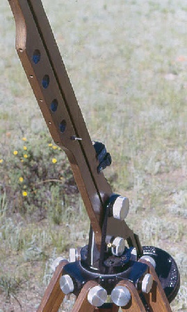
The arms are 1-3/4 x 3/4 inch oak. A piece of 5/8 inch aluminum plate was sawn out to fit against the lower end of the upper arm and a length of polished 1 inch steel rod with a flat filed on the end was screwed to the aluminum plate. An aluminum sleeve rides on this steel rod and carries barbell weights to counterbalance the upped end of the arms that carry the binoculars. The lower arm is equipped with three bright red and two bright white LED's that point toward the ground and are recessed well into the wood, out of direct vision to prevent glare. Either the red or white lights can be selected with a flick of a center off, three position toggle switch that is also recessed into the arm along with the necessary wires. This provides a convenient, glare-free field of light, directed down toward your lap when sitting, or your hands when standing for lighting any book or map you may be using. The groove that the wires follow runs along the upper side of the lower arm and is filled with a mixture of oak sawdust and wood glue. After sanding, staining, and finishing with clear coat it is almost invisible. The wires emerge from the lower arm and pass through a hole in the upper arm at a point between the uprights of the tripod head. They originally went to a battery that hung near the counterweights, but now simply go to a 4-pack of AA cells fixed to the upper arm with Velcro.
At the upper end of the arms is the mount that holds the binoculars. This is made of a group of aluminum castings and is where I departed from the design of all the binomounts I had seen up to that time. With those designs, azimuth motion around the sky or horizon had to be accomplished by moving the whole mount, arms and all - by walking around the tripod. This negated one of my requirements - that I be able to scan as much of the sky as possible from a stationary seated position.
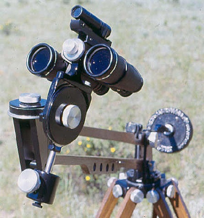
To get around that shortcoming I incorporated a second azimuth motion into the head at the upper end of the arms. This allows about 270 degrees of movement around the sky or horizon without having to rotate the whole arm assembly. The looseness of this motion is adjusted by the knurled knob at the top which compresses the top disk against teflon rings. The altitude motion is similarly implemented and adjusted by the knob on the side. The weight of the binoculars is counterbalanced around the altitude axis by a piece of 2 inch steel round stock that rides on a 1/2 inch stainless steel shaft.
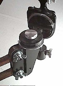
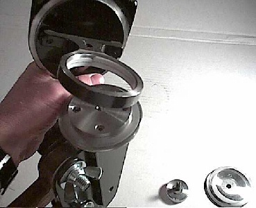
Both bearings are identical in function, basically consisting of a ring turning on a cylinder. The ring is adjustably clamped between the base flange of the cylinder and the top plate. A central thumbscrew (3/8-16) applies the adjustable clamping pressure. The top plate has a small hole which fits over a pin in the top of the cylinder to keep the top plate from turning as the bearing functions, which would tend to loosen or tighten the clamping screw. Below are a few photographs illustrating construction of the head. The first photo on the left gives a view of the "back" of the head.
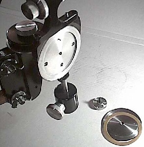
The photo on the left below shows the top plate of the azimuth motion removed and inverted to show how the parts fit together. The photo on the right shows the azimuth ring removed from its central cylinder.
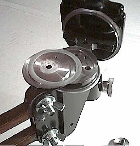
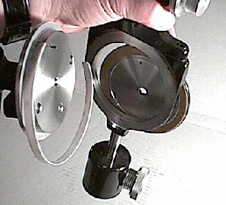
There is a Teflon strip between the outer ring and the central cylinder, as well as two plastic rings between the ring and the top plate and the ring and the base of the cyclinder's flange. This ensures that there is never any aluminum-on-aluminum friction which would gall and seize in short order. The plastic rings I beleive are polypropylene - cut from the tops of coffee can lids - a "Tupperware" feeling kind of stuff. Each of the Teflon and plastic parts has a very light coat of grease. The result is a buttery-smooth movement. The photos below show the altitude top plate removed and the altitude ring removed from its cylinder, revealing the similar construction.
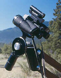
The binoculars attach to the mount with a knurled 1/4-20 screw into the objective end of the binocular's center pivot just as they would to a camera tripod with an L-bracket. This screw is provided with a knurled lock nut to ensure that the binoculars are well secured to the mount. Above the point between the barrels of the binoculars, mounted on a dovetail, is a red dot finder that is fitted with adjustment knobs and a dimmer control. This makes accurate pointing of the binoculars a snap.
This mount is a real pleasure to use. From either a standing or sitting position, a very large percentage of the sky can be accessed without changing position. The binoculars are easily steared with one hand. I usually use the small counterweight as the stearing handle. If you want to show another person what the binoculars are pointed at, simply push up on the arms and the object will remain in the field of view for the person standing behind you. When they have had their view, simply pull down the arms and continue from where you were. Nice.
BUT!! It was not always this nice!
This is in fact "model B" of this mount. Model A had some shortcomings that taught me a few lessons that resulted in my having to come up with model B. I'll fill you in on these mistakes below with the hope that I can prevent someone else from making the same mistakes. Examine the pictures below. On the right is the original model A, and on the left is the original model A head.
Note the funny angle that the counterweight shaft at the bottom of the arms makes. This was done to allow enough clearance to keep the battery that is hanging as a counterweight from running into the tripod legs. (This battery, which was meant to power the LED's in the lower arm as well as double as a counterweight was a bit of overkill. I conservatively estimated that it would power the LED's at full brightness continuously for 160 hours before recharge. I have since found a better use for this battery.) This funny angle was a big mistake. If the arms were placed near the upward position, the counterweights would be positioned further from the fulcrum so the center of balance would shift, which tended to raise the arms even higher. If the arms were positioned near the down position, the counterweights would be positioned closer to the fulcrum, so the center of balance would shift again and the arms would tend to fall even lower. This made it necessary to keep the tension of the height adjustment too tight for smooth operation.
Lesson learned: Keep the moment arms aligned and symetrical about the fulcrum.
Another problem with model A can be seen in the photo on the left. The central casting that the binocular rides on is too long, placing the binocular a couple of inches farther from the center of the altitude axis than it needs to be. This resulted in needing to have two of the steel counterweights mounted below the binoculars to keep this axis stable. The REAL downside to this was the extra weight needed at the lower end of the arms to counterbalance these counterweights! This was an inefficient use of materials that resulted in yet more junk to weigh the truck down on the way to an observing site.
Lesson learned: Keep the weight small at the long end of the arms to minimize the counterweight needed on the short end. This was not a lesson I really needed to learn, just one I shouldn't have ignored.
moment = weight x arm
In other words, if you have 5 pounds of binoculars 40 inches from the fulcrum, you have a moment of 5 x 40 = 200 inch-pounds. If the length of the other end of the arm is only 10 inches, then you are going to need 200/10 = 20 pounds to counterbalance the binoculars. So, keep the weight at the long end low, and keep the short end as long as is convenient. This minimizes the amount of dead weight you need to keep your binoculars flying smooth and easy.
You will also notice in the photos of model A that the oak boards are full width, further adding to the moment of the long arm.
As long as I was fixing the asymetry of the funny-angled counterweight shaft, I decided to reduce weight as well. To do this I poured a new casting that brought the binoculars closer to the center of the altitude axis. I also added a shaft to the other side of the binocular mount so I could increase the arm of that axis, which let me meet the moment needed to counter the weight of the binoculars with a single weight. That alone dropped the required weight on the short end of the arm by about 5 pounds. Further reduction in weight was accomplished by sawing off a bit of the heavy oak arms, tapering them down along their length then leaving them full width only at the point that they mate to their respective ends where the bolts go through. Holes were drilled between the LED's in the arms for further weight reduction.
By sawing out a new piece of aluminum to attach the lower end's counterweight shaft without the goofy angle, the symetry problem was reduced to almost zero. Now it's all smiles in Bino-Mount Land. :)
This was a fun project and about as much wood working as I care to do, but the results justified the material. One drawback is that this binomount almost counts as an extra telescope when traveling; but when a break from guiding long-exposure photos is needed, it is sure nice to just flop down into my lawn chair, lean back and put my feet up, and have the sky-sweeping power of binoculars instantly available without having to hold them up. Why don't you build one too?
- Jim Sapp
Summer, 2003