A Prototype Spectrohelioscope
of the Arcetri Layout
using Anderson Prisms in the Petit Arrangement.
A work in progress, this document will be updated as progress warrants.
Last updated: 10 May, 2003.
of the Arcetri Layout
A work in progress, this document will be updated as progress warrants.
Last updated: 10 May, 2003.
The typical implementation of Anderson prisms requires horizontal spectroscope slits so that both prisms can be mounted on the same motor shaft which keeps them in perfect synch. However, the Arceti spectroscope layout requires vertical slits. To overcome this dilemma, my original intention was to use a Dove prism (an image rotator) in each of the collimator lens light paths to twist each light path through 90 degrees so that the orientation of the slits could be horizontal.
Unfortunately, the Dove prisms I acquired were of poor optical quality, which forced me to change my plan and live with the vertical slits, mounting the Anderson prisms on separate motors in the Petit arrangement. This requires precise regulation of motor speed to keep the spinning prisms synchronized and is accomplished by finely adjustable separate regulated power supplies for each motor.
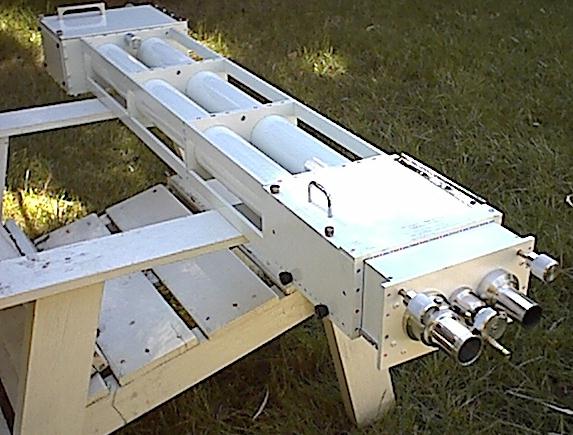
Since it is a prototype, the instrument is built in three easily separable main sections so that experimentation with differing parts can be accomplished. The three sections are as follows:
1. The main COLLIMATOR and SLIT section consists of a strong framework of aluminum bar and plate that serves not only as a structure to hold the two tubes of the Arcetri spectroscope, but also as a universal mounting point for the small test telescope (initially, a 66mm refractor of about 800mm focus with a Barlow lens to double the focal length) or as an attachment point of the instrument to a larger telescope or an equatorial mount. Each of the two spectroscope tubes are fully baffled refractors with draw tubes that terminate with the slit holders.
Focusing of the collimator lenses on the slits is accomplished by turning a single central threaded rod which simultaneously moves the two draw tubes. The slits are easily interchangeable, and the effective focal length of the collimator lenses can be increased by the addition of a pair of Barlow lenses to the draw tubes.
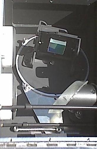
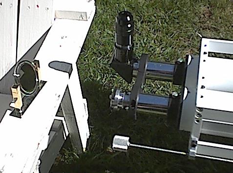
2. The GRATING section is attached to the collimator section with four large thumbscrews. This section contains the diffraction grating and the diagonal mirror which together bend the light path through a U-turn and disperse the sunlight into a spectrum. A hinged door on top of the box as well as two panels held in place with thumb screws provide access to the mirror and grating mounts.
The photo above shows the grating box installed. On top of the box is the little white protective cover that came with the grating. This cover is glued to a Velcro strap. When not in use the strap wraps around the grating mount and holds the cover in place to keep the grating clean and protected.
The diffraction grating is held in a thumbscrew-replaceable cell which can be exchanged with other cells holding additional gratings for experimentation. These cells are held in the grating mount with thumbscrews.
The mount is adjustable for tilt and can be rotated about its vertical axis by loosening two small thumbscrews for selecting which of the grating's orders is to be used. Once these thumbscrews are tightened, the mount's base is held firmly to a tangent arm for fine tuning of spectral lines. The lead screw of the tangent arm is fitted with an anti-backlash spring and an extension rod which leads to the eyepiece end of the instrument for convenient adjustment.
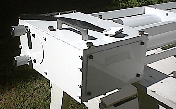
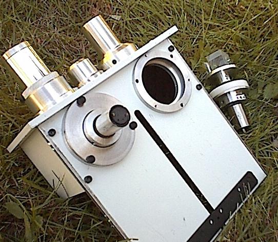
3. The INPUT/OUTPUT section is similarly held to the collimator section with four large thumbscrews and contains the image synthesizer, the entrance port which brings light from the telescope, and the exit port for the eyepiece. The bearings for the slit-focusing lead screw are also mounted here.
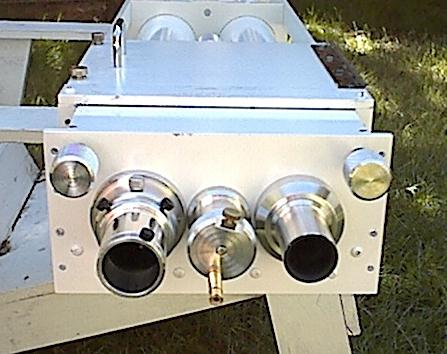
The entrance port (on the right in this picture) is made to fit in any 1.25 inch telescope focuser and is extra-long to provide some lattitude for telescope focus adjustment while maintaining a closed, shielded light path.
The exit port consists of an aluminum draw tube which rides on three Teflon rings for a smooth sliding fit, similar in construction to the collimator's draw tubes. It is fitted with an adjustable stop and will accept standard 1.25 inch accessories and provides about one inch of eyepiece or relay lens travel. This draw tube can be rapidly removed and exchanged with others of varying lengths to meet the requirements of any relay lens, star diagonal, or eyepiece arrangement.
The slit-focusing lead screw has a �-20 thread providing 0.050 inch movement per turn and is mounted in three ball bearings, two in the moving synthesizer assembly between the entrance and exit ports, and one mounted to the collimator assembly's frame between the collimator tubes. The lead screw's shaft is an easy sliding fit in these bearings so that the synthesizer mounting plate (see below) can be moved to various positions without disturbing the slit focus. The focusing knob can also slide along the length of the shaft and is provided with a thumbscrew to lock it in position and a handle for rapid traverse. In use, the lead screw shaft is captured longitudinally by a thumbscrew and collar fitted with a Teflon washer that resides between the spectroscope tubes, opposite the bearing on the collimator assembly.
When the synthesizer box is removed from the collimator assembly, the focusing lead screw can either be left with the collimator by simply removing the focusing knob, or it can be removed along with the synthesizer box by removing the retaining collar between the collimator tubes.
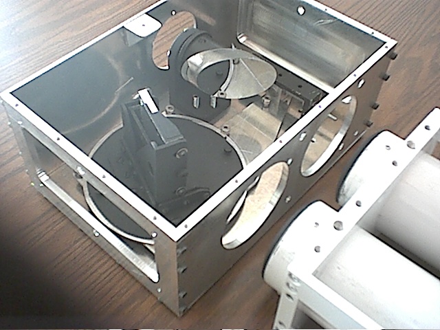
The synthesizer box proper is constructed of � inch aluminum plate that is hollowed out to reduce weight yet retain strength. A hinged door allows access to the interior for adjustment and replacement of the slits or changing out any Barlow lenses.
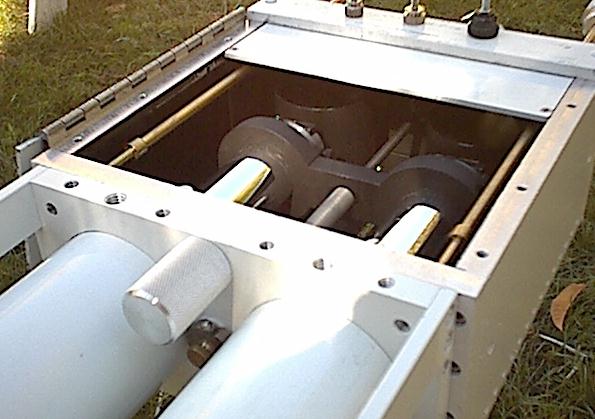
The prism assemblies, entrance/exit ports, and slit focusing control are fixed to a plate that slides in channels milled into the sides of the box. This whole assembly can be extended from the box and clamped in position at 1/4 inch intervals over a 2.5 inch range to provide a variety of stations for experimenting with different Barlow lenses and focal positions.
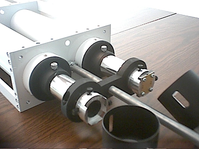
The prisms are each provided with a cylindrical shield to act as both a light shield and baffle for air currents and are painted with high temperature flat black paint. The aluminum construction of the unit should act as a suitable heat sink to carry away the heat from the focused sunlight at the entrance prism. If not, further provision for cooling the entrance prism's shield can be added later.
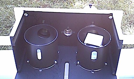
The input side of the entrance prism's cylindrical shield is a round hole to allow a 1 inch diameter solar image to the spinning prism, while the side of the shield adjacent to the slit is a 1/4 inch vertical slot. This is to allow the shield to intercept the majority of the heat and light before it reaches the entrance slit. The exit prism's shield likewise has a slot on the side adjacent to the exit slit to act as a baffle for stray light within the box and a round hole on the opposite side to provide for a 1 inch diameter light path to the eyepiece.
Each prism/motor assembly is held in place with three thumbscrews and is installed and removed from the outside of the box without the need to disassemble any other components. This photo shows the bottom side of the assembly with one motor installed and the other laying nearby. The plate that the prism assemblies are mounted to is reversible and can be used to mount a different synthesizer for further experiments.
CURRENT MECHANICAL COMPONENTS:
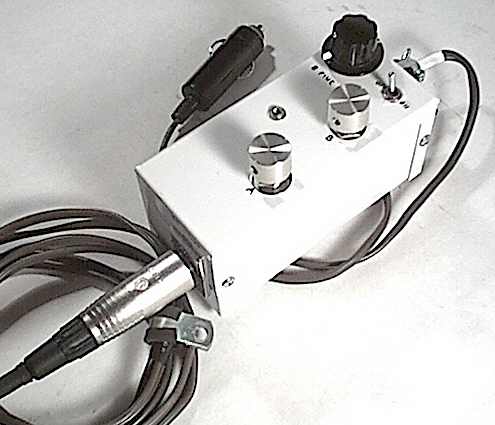
Petit motors: Small high-torque DC gear motors that operate smoothly from about 2 volts to over 20 volts. They seem happiest between about 6 and 12 volts, where they provide about 300 to 600 RPM (if I remember correctly). Each motor is powered by an LM317 adjustable voltage regulator. One of the regulators is provided with an additional 10-turn potentiometer for precise matching of speed to the other motor. Although not really needed, since the motor speeds can be independently varied, both motor mounts are provided with independent rotation adjustment to counteract synchronization drift.
Grating Movement: 6.5 inch tangent arm driven by 32 TPI lead screw in ball bearings with anti-backlash spring.
I was pleasantly surprised to see that the spectral resolution of this thing is tremendously better than my little bench top spectrometer with a flint prism.
With a 0.003" slit the D2 line of the sodium pair would not quite show its faint companion. With a 0.002" slit the D2 line was easily seen to be double and I could easily see 7 faint lines between the D1 and D2 sodium lines and suspected two more. With a 0.001" slit I could easily see 9 faint lines between D1 and D2 and could tell that there were two more just past the resolving power. At 0.001" the brightness falls off quite a bit. I suspect brightness will not be as big a problem though, when light from a telescope will be focused on the slit instead of the feeble light reflected from the back of a metal clock.
I was surprised also by how wide the H-a line is. When I first saw how narrow the dark sodium lines are, I was a little worried about not being able to keep only the H-a light on the exit slit when in spectrohelioscope mode, but the hydrogen-alpha line is wide and should not be a problem.
It was disappointing to see how much brightness is lost when tuned to the H-a line too. Not only does the 5000A grating efficiency drop off a lot in red light, but so does the efficiency of the eye. I can see now that my next grating will probably be one blazed nearer to 6000A.
I was also a bit disappointed by the loss of brightness and image quality when using a cheap pair of Barlow lenses in each tube to extend the focal length. On the optical bench with an illuminated target the image looked very good, but in the real world it made me frown a bit, though I will need to experiment some more when I get the synthesizer finished and feed real telescope light into it. I did not get a chance to try out the better pair of negative achromats I have though. Perhaps they will work better.
The speed control works very well. Using normal voltages it is possible to independently vary the speed of the prisms from about 1 revolution per second up to around 20 (much more at higher voltages), and the fine speed control is very forgiving. It is easy to achieve synchronization at any speed.
I noted that at the slower speeds (say 10 to 30 image sweeps per second) the natural movement of the eye will on occasion come into synch with the slit movement and a bright instantaneous slit of light appears. For me this happens at a frequency of about once or twice per second. At higher prism speeds of about 60 to 80 sweeps per second these fleeting blips of brightness are much less annoying and appear quite a bit dimmer in relation to the background image. Running the motors at higher sweep rates than this tends to heat the motors up a bit.
No difference in the apparent brightness of the image is seen at the differing sweep rates, so it appears that running the prisms at higher speeds has a clear advantage.
When using a ~350mm f.l. achromat as an eyepiece the image appears rock solid (once the motors are synchronized) and no image wobble from the not-quite-centered output prism is seen. However, when using a 125mm eyepiece, image jitter becomes apparent. My intention is to eventually use a 40mm eyepiece so this jitter will be unacceptable for my purposes and needs to be rectified if this synthesizer layout is to be retained.
The image is quite dim even when using a 100-watt bulb in the bench collimator. I found that by replacing the 30mm grating with a 50mm grating the brightness was improved quite a bit. For further experiments I will need to get real sunlight into this thing.
It is now apparent that this prototype is becoming much too heavy and bulky to use mounted to the side of the 6 inch refractor in equatorial mode, so for now the SHS is on the back burner until I can build a heliostat to feed the telescope sunlight. This will make adjustment and experimentation with the setup much easier.
A suitable heliostat mirror has been obtained and I have completed a stepper motor controller for the heliostat mount The controller is based on David Rowe's design and generates the signals necessary to enable two stepper motors to provide fast slewing, tracking, and slow motion control of the heliostat mount in both right ascension and declination via a handheld control paddle.
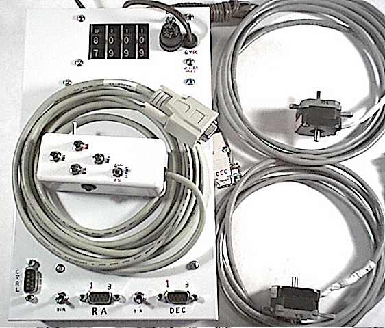
The hand paddle fits nicely in the palm of my hand and all controls are easily reached with the thumb. This will make centering and tracking of solar details very easy once the mount is complete. The mirror will be mounted in a cradle which will keep the mirror surface centered along the optical axis of the telescope, which will be mounted horizontally on two stable tripods. At least that's the plan at this point...
It appears that larger (and/or denser) prisms would be an improvement in this Petit arrangement. Even though these prisms provide a fairly wide light path, it is possible to adjust the motor synch to get 1/2 of two images in the field of view. It can also be set to see a black vertical line (assumed to be the prism edge) slowly scan across the field of view even though the image remains set.
These prism motors are quite noisy - they sound just like one of those nasty Meade goto SCT's and can be heard from many yards away. This will NOT be acceptable in a finished SHS. For this reason alone a different synthesizer setup will be used in a final instrument, which will probably employ Anderson prisms mechanically joined together, similar to Ken Florentino's setup (the tank prisms have already been acquired). This will eliminate one motor and also allow the single motor to be mounted inside the synthesizer box with proper sound proofing. The single motor can then be geared up, which will eliminate the need for 24 volt power to achieve the higher spin rates in the current setup. (The spin rate target for a finished instrument will be on the order of 80 to 100 image sweeps per second.) Since my eyes can see 60 cycle flicker in flourescent and neon lights, this is a reasonable target in light of the observations noted above.
This will also eliminate the problem of motor synch drift, which is not really a big issue unless the instrument is set up for public viewing, in which case regular attention would be required to keep the image in one piece.
- Jim Sapp