by Jim Sapp
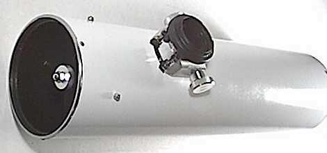
One of the more troublesome aspects of building telescopes can be coming up with a design for a suitable focuser. The simple sliding-tube type is always an easy solution, but can be very tedious when changing eyepieces or trying to achieve a critical focus with a high power eyepiece.
The simple helical design can be made with a very low profile, and is easy to construct with off-the-shelf plumbing parts if you don't mind having the eyepiece or camera rotate when focusing or having a very limited smooth-working travel. A non-rotating helical design can be made with a little more work, but the single-lead helical designs generally provide too slow, or too fine a movement for use with telescopes that have a focal length much longer than twenty or thirty inches.
The rack and pinion type focuser is fine for refractors and Cassegrains, but to be stable, is often made a bit taller than many people would like on their Newtonian reflectors - not to mention the difficulties encountered in constructing a smooth working unit without a broaching tool or shaper for the rack's keyway.
Many people, like me, have built Crayford type focusers similar in design to the two drawings below.
[For those that would like to build a focuser of the type pictured above: it is simply two pieces of 2 inch aluminum channel, one fixed to a base plate with a piece of angle, and the other attached to the base plate with a hinge. The fixed piece has an additional piece of angle screwed to the interior, to which four small ball bearings are mounted on stand-offs, which the focusing tube rides on. A 3/16" or 1/4" brass or steel rod passes through the hinged piece to serve as the pinion shaft, and a pair of springs provide the pressure that grips the tube between the pinion shaft and bearings.]
There is also the single-piece Crayford option pictured below.
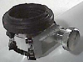
This is a one inch tall, low-profile unit for a short photographic Newtonian. It is light and simple to make but still prone to allow dust and moisture into the telescope interior or focuser bearings.
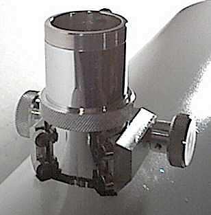
After knocking around a few ideas I have come up with a single-piece Crayford design that has worked very well and is still fairly simple to make. It provides the smoothness and ease of use that typify Crayford-type focusers, is very compact with a very low profile, and can be made relatively impervious to dust and moisture. Theoretically, it can be made completely on the drill press (though I cheated a little with a lathe).
For the body of the focuser, I have used aluminum plate as thin as one inch (or even slightly less) for a really low profile, but 1-1/2 or 2-inch thick material gives a little better control over bearing alignment when final assembly time comes since the bearing pairs can be farther apart. The wood workers among us could probably get by with a chunk of good solid hardwood or even plexiglass or other plastic.
The length of the focus tube can be modified as required, and changed out in an instant. I keep a long one and a short one in my eyepiece case for switching between straight-through and right-angle viewing on instruments with limited back-focus adjustment (Cassegrains).
The design should be made apparent by the illustrations. As with the other designs above, the focus tube rides on four tiny ball bearings mounted on screws with spacers or standoffs at the bottoms of four holes drilled chordally into the body of the focuser. The pinion shaft is a length of 1/8" steel rod, which turns in holes drilled through a pair of short lengths of 1/4" brass rod (the plungers).
These plungers are free to ride lengthwise in holes drilled into the focuser body, and impart the tension of their respective compression springs to the pinion shaft and focus tube.
The springs are captured and loaded by the action of two 5/16" set screws that are threaded into the plunger holes and fixed in place with thread locking compound. The hole through the focuser body that the pinion shaft passes through is over sized to allow plenty of movement for the pinion shaft to be pressed against the focus tube. The sides of this hole, and the holes for the four bearings of course, break through the inner wall of the large hole in the body to engage the focus tube.
A small metal plate can be mounted to the exterior to seal the bearing holes against dust and moisture, and the shoulder of the eyepiece adapter on the end of the focus tube effectively seals the large hole when the tube is fully racked in. Teflon washers on the pinion shaft between the focus knobs and the body of the focuser serve as low friction seals or covers for the over-sized pinion shaft hole.
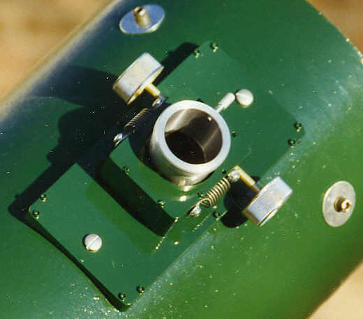
Any sort of mounting method can be used with this focuser. It can be mounted directly to a flat surface, or adapted to a curved tube wall, or be bored to accept a refractor's draw tube. For one of my 1-1/4 inch models I tapped threaded holes in the bottom of the body to mount a 2-inch flanged barrel. This allows me to use the focuser as a 1-1/4 inch eyepiece adapter in any other 2-inch focuser (like my old helical job), and only adds about 1-1/2 inches of height.
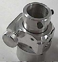
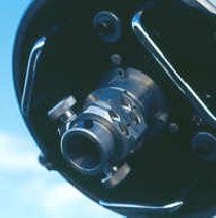
The back plate of one of my Cassegrains is bored to accept this 2-inch "adapter" and two of my refractors will accept it as well. I can move this focuser from scope to scope just as quickly and easily as moving an eyepiece!
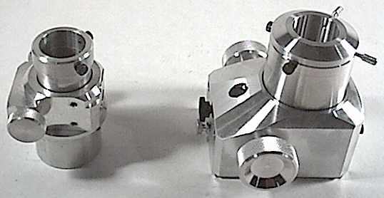
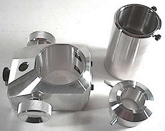
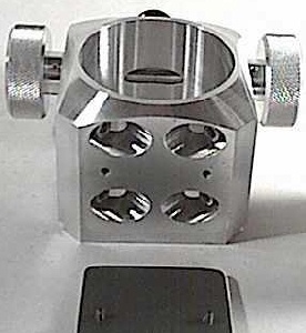
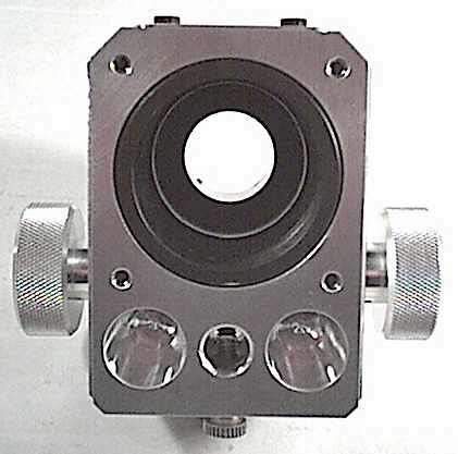
You can, of course, scale this design up to any size you like. The 2 inch focuser pictured here is equipped with a set of threaded holes in the base for future universal attachment. The base of the body is also dovetailed to fit an adapter plate on a Newtonian telescope tube to allow for a bit of adjustment along the longitudinal axis of the tube. The two large holes at the bottom in this picture were bored to reduce the weight of the unit a bit and reach just short of the plungers. The 1/2 inch hole between them accepts a rod for mounting a solar projection screen or camera body for afocal photography.
The first step is to select the ball bearings and tubing you will use, so that you will have accurate dimensions to lay out the rest of the design. For tubing, I use standard 1-1/2 inch aluminum, then turn up a 1-1/4 inch adapter on the lathe and fit it with a small thumb screw or two to lock the eyepiece in. This adapter is made to be a tight fit in the tube, pressed in (using a drop of 'super glue' as lubricant), then the inside of the tube is threaded and painted flat black to minimize internal reflections. A handy source for the ball bearings are old muffin fans from the power supplies of computers. Each fan will provide one or two bearings, depending on the brand.
The next step is to make an accurate scale drawing (at least double-scale) using the known sizes of your tubing and bearings to find the dimensions and locations for the remaining features.
To begin, saw two pieces (cuts A and B in the plan drawing above) off of one end of a rectangle of the body material and mill (or file) them true to form a centered 90 degree rooftop shape on the end. This will provide flat surfaces to drill the bearing holes into. This is to help ensure accurate hole placement. It is much easier to drill an accurately placed hole into a perpendicular face than into a slanting one. The opposite end of the rectangle can then be supported in a V-block for the bearing hole drilling operation, or a tilting drill press table can be used. The holes can then be drilled and tapped for the bearing support screws, and then the body is placed on one side to drill the pinion shaft hole.
Next, the rooftop is cut off (cut C) and milled (or filed) square, and the plunger holes drilled and tapped. Drill or ream the plunger holes to slightly larger than 1/4" (drill size F works good) to allow an easy sliding fit for the plungers, and only tap threads as deep as you will need for the set screws to do their job of loading the springs. (You may want to have two or three different pairs of springs on hand to experiment with before committing to final assembly. At this point, the large hole for the focus tube is drilled and/or bored. This operation could be done with a hole saw, plenty of coolant, and some patience on the drill press. Perhaps even a circle cutter working outward in steps could be used. This is where I cheated with the lathe.
After all the critical holes have been drilled, the outside lines of the focuser body can be prettied up on the lathe, the disk sander, or with a file.
The holes in the plungers should be drilled a little oversized to allow the pinion shaft to turn very freely. A number 30 (0.128") drill is fine for 1/8" rod. It is advisable to make a small fixture to keep the focus tube squarely aligned and centered with respect to the focuser body when installing the four bearings, especially when making a very low profile unit.
Overall, I have been very pleased with this focuser design, and have found no negative attributes with it yet.
Steady skies!
Summer, 1998
(updated Spring, 2003)